Low Voltage 12V Relay Driver Using LMC 555 Timer IC Circuit Diagram Before we begin, we must know what is the relay how it works before we use it to power high voltage devices. The relay module is an electrically operated switch that can be turned on or off deciding to let current flow through or not. They are designed to be controlled with low voltages like 3.3V like the ESP32, ESP8266, etc, or 5V like your

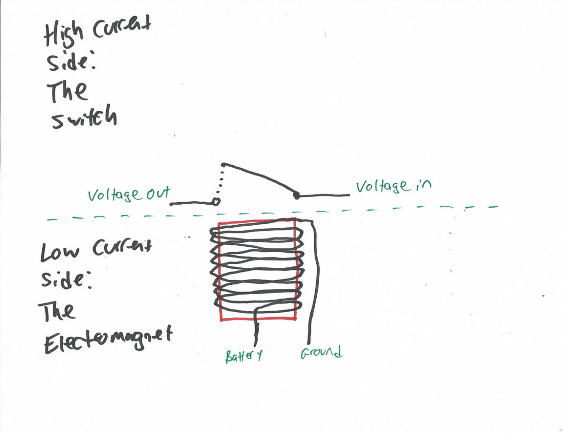
It is much lower that the voltage that the lamp works with. We need a module to make it possible to control the high voltage/large current with Arduino. That is what a relay can do. The relay is an electrically operated switch, it acts like a soldier, accept low voltage signal commands for Arduino, and then control the high voltage gun on/off.
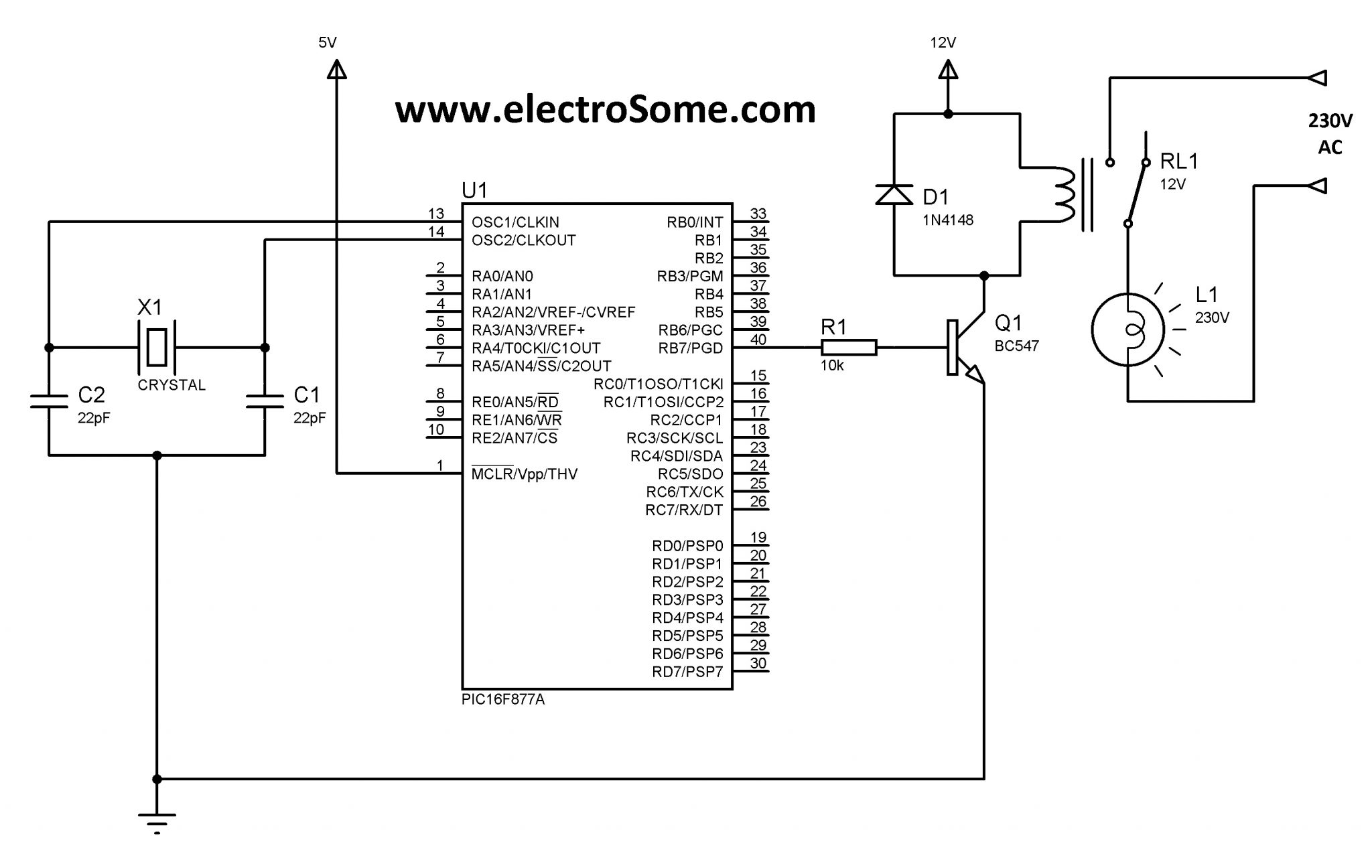
Use Relays to Control High Voltage Circuits with an Arduino Circuit Diagram
Arduino Relay Tutorial for High Voltage Control. As with most things Arduino, we're going to need a little code and we'll need an input. While it's certainly feasible to do this project without any inputs (using a timer loop, for example), we're going to use a photoresistor. A photoresistor is a resistor that changes its resistance This project will teach you how to control a 120V appliance using an Arduino Uno and a Relay Module!
This code is designed to control a relay, which in turn can control a high-voltage appliance (up to 250V) using a push button. The behavior is such that pressing and releasing the button once will turn the appliance on, and pressing it again will turn it off. This is often referred to as a "toggle" or "sticky" push button behavior.
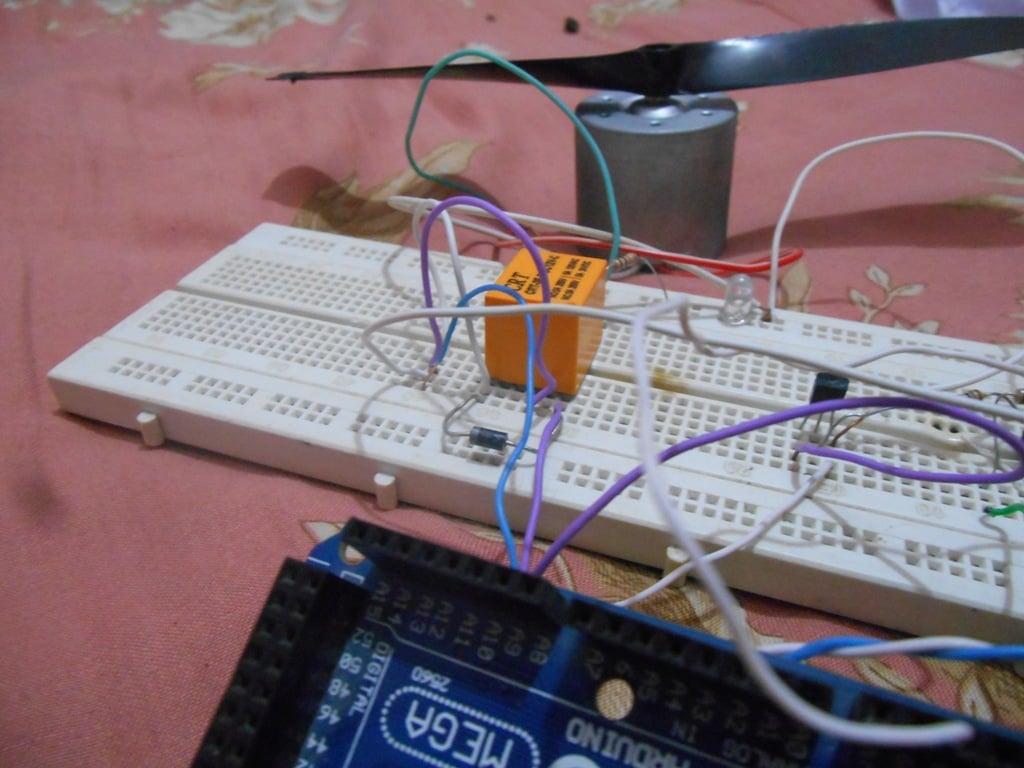
Arduino Relay Tutorial Circuit Diagram
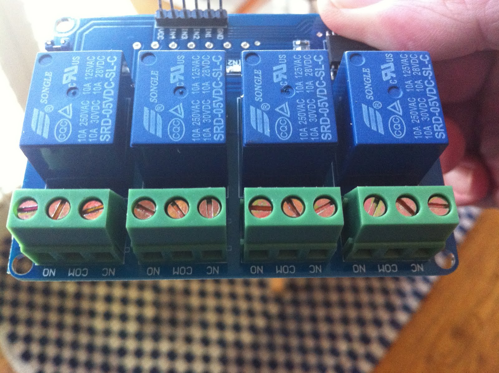
As an example for this Arduino Relay Tutorial we will use the HL-52S 2 channel relay module, which has 2 relays with rating of 10A @ 250 and 125 V AC and 10A @ 30 and 28 V DC. The high voltage output connector has 3 pins, the middle one is the common pin and as we can see from the markings one of the two other pins is for normally open Please click this link to see the full article: http://www.allaboutcircuits.com/projects/use-relays-to-control-high-voltage-circuitswwith-an-arduino/Circuits