Schematic of proposed low noise amplifier Circuit Diagram ECE145A/ECE218A Design of Low Noise Amplifiers Set up a biasing circuit such as the one below. Select a large signal device model from the Analog/RF - RF Transistor/Packaged BJT library. Then perform a DC simulation. To see the results of the DC simulation, you go to the Simulate Menu > Annotate DC solution.

cularly valuable because any low frequency or burst noise can be observed. If the pre amp does not dominate the noise generated from succeeding stages (with the gain control at a maximum) then these stages need to be examined! The full design of a general-purpose au dio preamplifier can be quite a problem,
Step Guide to Designing a Low Noise Amplifier for ... Circuit Diagram
But there is more to designing low noise circuits than choosing the lowest voltage noise density (e n) amplifier for a given frequency band. As shown in Figure 2, other noise sources come into play, with incoherent sources combining as a root sum of squares. Figure 2: Op Amp Circuit Noise Sources First, consider resistors as noise sources.
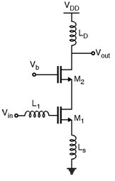
Low Noise Amplifier Design and Optimization IV.1 CMOS LNA Design and Optimization Overview Low Noise Amplifier (LNA) is the most critical part of a receiver front end, in term of the receiver performance. Many circuits with different configurations have been proposed for LNA, in different applications.

PDF EE215C B. Razavi Win. 13 HO #2 Low Circuit Diagram
In this tutorial, we will learn the step-by-step guideline of a Low Noise Amplifier (LNA). For this tutorial, we will design an ISM band LNA for 2.4GHz to INA300 / INL300 / INE300 / LEAP Designing a custom IoT product RF Radio / Radio Component Design Antenna Design RF Circuit Design and Measurement Training RF Circuit Design and
